An evidence review of active and passive interference, frequency selection, signal margin, transmitter power, housing effects, calibration, and field verification.
Electromagnetic interference can degrade HDD tracking before a receiver loses the transmitter signal. Depth, pitch, roll, and position may still appear on screen even when the margin between the transmitter field and the surrounding electromagnetic environment has narrowed.
Current platforms address this risk with different combinations of frequency selection, interference analysis, signal monitoring, transmitter power control, and low-frequency operating modes. Examples include DigiTrak Falcon and SuperCore, Subsite Marksman Plus, and Underground Magnetics locating systems. None of these features removes interference by itself. Reliability depends on the complete locating system and on the conditions along the bore.
| Key findings: Published maximum depth does not predict tracking reliability under interference. Signal margin, field distortion, calibration, and system configuration can become more important. Active interference and passive interference are different failure mechanisms. A frequency scan can reveal active noise, but it may not reveal distortion caused by nearby steel or rebar. Frequency flexibility gives crews more options to improve signal conditions. It does not guarantee accurate position or depth. Higher transmitter power can improve a weak received signal, but it does not necessarily correct a magnetic field that nearby metal has already distorted. Housing geometry, calibration quality, changing conditions along the bore, and receiver-to-drill telemetry can create symptoms that resemble interference. The cited source set does not provide a controlled independent test that establishes one current platform as universally more reliable than the others. |
Research Scope and Evidence Basis
This review synthesizes product manuals, transmitter specifications, troubleshooting guidance, and an industry standard listed in the References section. Product-specific ranges, battery-life figures, and platform features come from manufacturer documentation and should be read as manufacturer-reported specifications rather than independent comparative test results.
The evidence base supports a qualitative comparison of interference-management approaches. It does not support a universal accuracy ranking across DigiTrak, Subsite, and Underground Magnetics under identical depth, housing, calibration, and interference conditions.
Two limits are especially important: the source set does not provide a manufacturer-independent SNR threshold that guarantees a stated HDD locating accuracy, and active-interference scans do not by themselves rule out passive magnetic distortion.
1. Active and Passive Interference Require Different Responses
Active interference is electromagnetic energy generated by another source. Subsite documentation cites examples such as energized utilities, traffic-control loops, alternators, radio infrastructure, and cathodic-protection systems. These sources can produce signals that compete with the downhole transmitter.
Passive interference does not require an external electromagnetic signal. Steel, rebar, wire mesh, buried metallic pipe, fences, drill pipe, and other conductive or ferrous objects can distort the transmitter’s magnetic field.
That distinction changes the diagnostic approach. A crew can often detect active interference by surveying the proposed bore path with the transmitter inactive and comparing available frequencies. Passive interference can remain hidden during that scan because the metal is not generating noise. The problem may appear only after the transmitter enters the affected area.
A quiet jobsite is therefore not necessarily a clean magnetic environment.
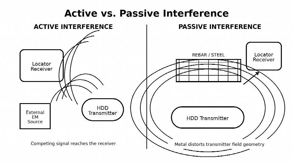
Figure 1. Active interference adds competing electromagnetic energy; passive interference distorts the transmitter field around metal.
Table 1. Interference mechanism and first-line response
| Interference type | What changes | What the crew can check first |
| Active electromagnetic interference | Competing signal reaches the receiver | Survey the full route and compare usable frequencies |
| Passive interference | Nearby metal distorts transmitter-field geometry | Identify rebar or steel; evaluate supported low-frequency modes and verify readings |
| Mixed conditions | Noise and field distortion can occur together | Compare several frequencies, retain low-frequency capability where supported, and verify critical crossings |
2. Maximum Depth Is Not a Reliability Metric
Locator specifications often emphasize maximum depth or range. Those figures matter, but they do not show how much usable signal margin remains when the receiver is exposed to noise or when nearby metal changes field geometry.
Subsite states that actual range varies with environmental conditions, operating frequency, and the downhole housing. Its Noise Floor Analyzer estimates usable range from measured interference. Underground Magnetics uses a related approach in the Mag X platform with SNR and Range Forecast functions.
A more useful field concept is signal margin: the usable transmitter signal at the receiver relative to background interference and measurement uncertainty. A 40 ft crossing under reinforced pavement and electrical infrastructure can therefore present a harder locating problem than a deeper bore through cleaner ground.
3. Frequency Selection: Useful, but Not Universal
Frequency changes how the locating system interacts with the electromagnetic environment. For active interference, crews generally need a frequency with less competing noise. Modern systems improve this decision by providing multiple usable frequencies instead of forcing the entire bore onto one fixed channel.
Current DigiTrak Falcon and SuperCore platforms provide broad frequency flexibility. Subsite Marksman Plus includes bore-path interference analysis and frequency recommendations. Underground Magnetics transmitters such as the Echo 75XF provide multiple discrete operating frequencies.
The lowest frequency is not automatically the best choice. If active noise is concentrated in one part of the spectrum, moving higher or lower may improve signal margin. Passive interference creates a different problem: Subsite documentation states that lower beacon frequencies typically reduce passive-interference effects, while DigiTrak and selected Underground Magnetics transmitters support sub-kilohertz operation for applicable conditions.
Underground Magnetics specifies an operating-frequency range of 0.325 to 41 kHz for the Echo 75XF. This is a manufacturer specification for that transmitter, not an independent measure of locating accuracy.
Table 2. Practical frequency strategy by interference condition
| Condition | Primary strategy | Important limitation |
| Active electromagnetic noise | Find a cleaner usable frequency | A cleaner scan does not rule out passive distortion |
| Passive metal distortion | Consider lower or sub-kHz operation where the system supports it | Lower frequency does not guarantee correct depth or position |
| Mixed active and passive interference | Compare several frequencies and preserve low-frequency options | Verification remains necessary when indicators disagree |
4. Signal-to-Noise Information Adds Context to Raw Signal Strength
A strong transmitter signal does not necessarily indicate a reliable locate if the background noise is nearly as strong. For this reason, signal-to-noise information can be more informative than raw signal strength alone.
Underground Magnetics displays SNR in the Mag X interface and provides Range Forecast functionality. Subsite uses a related concept with its Noise Floor Analyzer, which estimates usable range from measured interference.
The practical value appears when two sites use the same transmitter, housing, receiver, and depth but have different electromagnetic backgrounds.
Table 3. Simplified signal-margin example
| Example | Transmitter signal | Background | Observed behavior |
| Site A | Moderate | Very low | Readings remain stable |
| Site B | Stronger | Also strong | Depth and position become unstable |
Raw signal strength could make Site B appear better. Signal margin points in the opposite direction. The cited sources do not establish a manufacturer-independent SNR value that guarantees a specific HDD locating accuracy, so operators should treat SNR and noise-floor information as diagnostic indicators rather than universal pass/fail thresholds.
5. Transmitter Power Helps When Signal Is Weak, Not When Geometry Is Wrong
Modern HDD transmitters often provide several output levels. Higher power can increase the received signal when depth, attenuation, or active background noise reduces signal margin, but it also shortens battery life.
Underground Magnetics lists three output levels for the Echo 75XF. The figures below are manufacturer-rated specifications.
Table 4. Echo 75XF manufacturer-rated power, depth/data range, and battery life
| Power mode | Manufacturer-rated depth/data range | Manufacturer-rated battery life |
| Low | 115 ft | 100 hr |
| Medium | 180 ft | 60 hr |
| High | 246 ft | 11 hr |
The engineering tradeoff is clear: more output can create more signal margin, but it consumes battery capacity much faster. Power does not, however, act as an interference override.
If steel changes the shape of the transmitter’s magnetic field, increasing transmitter output does not necessarily restore the original geometry. The receiver may simply detect a stronger distorted field.
6. Housing and Calibration Can Mimic an Interference Problem
Housing compatibility
The transmitter housing is part of the locating system, not only a mechanical enclosure. Housing length, diameter, slot geometry, transmitter position, and manufacturer requirements can affect how efficiently the magnetic field leaves the steel housing.
Subsite states that current beacons use automatic tuning circuitry to adjust to the housing being used. DCI also publishes model-specific housing requirements for some transmitters, including slot dimensions intended to support proper signal transmission and battery performance.
A transmitter that physically fits inside a housing is therefore not automatically an electromagnetically correct combination. When tracking performance becomes weak or inconsistent, check the exact transmitter and housing models, housing dimensions, slot placement, transmitter position, wear or modification, and the manufacturer’s compatibility requirements.
Calibration
Not every incorrect depth reading comes from electromagnetic interference. Calibration errors can create similar symptoms and can affect every later reading.
DCI troubleshooting guidance tells operators to verify calibration above ground at a known distance and to repeat calibration in a clean environment when readings are incorrect. Underground Magnetics warns against calibrating around strong active or passive interference. Subsite’s Marksman manual specifies a 10 ft calibration distance and warns against nearby passive-interference sources such as the drill and drill pipe.
A useful troubleshooting sequence is:
- Check the locating environment.
- Check and verify calibration at the manufacturer’s specified distance.
- Confirm the transmitter and housing configuration.
- Compare another usable frequency.
- Treat the problem as unexplained equipment failure only after the preceding checks fail to explain it.
7. Interference Can Change Along the Bore
Conditions measured at the entry point do not necessarily represent the entire crossing. The electromagnetic environment can change over a short distance as the bore passes through open soil, reinforced pavement, buried utility congestion, traffic-control loops, steel pipelines, overhead power infrastructure, or reinforced structures.
Subsite’s Bore Path Analyzer is designed around surveying conditions along the planned bore path. Underground Magnetics also instructs operators to walk the route and evaluate frequencies before drilling.
The practical consequence is simple: a frequency that performs well near the drill can become a poor choice farther along the bore. A pre-bore survey should therefore follow the full planned route, not only the entry area.
8. What Current Platforms Actually Provide
Manufacturer documentation shows three different but overlapping approaches to interference management. The feature sets below describe diagnostic and control tools; they do not establish cross-brand accuracy or superiority.
Table 5. Manufacturer-documented interference-management approaches
| Platform | Documented approach | Evidence limitation |
| DigiTrak Falcon / SuperCore | Broad frequency selection, supported Sub-k modes, multiple transmitter power levels | Frequency count alone does not prove higher accuracy |
| Subsite Marksman Plus | Bore Path Analyzer, frequency recommendations, Noise Floor Analyzer, Extended Range Mode | Subsite states that Bore Path Analyzer measures active interference, not passive interference |
| Underground Magnetics Mag X | SNR display, Range Forecast, multi-frequency transmitter support, selectable transmitter power | Feature set does not establish cross-brand superiority |
DigiTrak Falcon and SuperCore
Current DigiTrak systems emphasize wide frequency flexibility. SuperCore transmitters support many Wideband and Sub-k frequency options, while supported Falcon systems provide frequency-scanning and selection tools. This gives crews more ways to move away from active interference, but it does not prove that every selected frequency will produce an accurate locate.
Subsite Marksman Plus
Marksman Plus combines Bore Path Analyzer, active-interference measurements, frequency recommendations, Noise Floor Analyzer, and Extended Range Mode. One limitation is explicit in Subsite documentation: Bore Path Analyzer measures active interference rather than passive interference. A favorable scan therefore does not rule out rebar or buried steel.
Underground Magnetics Mag X
Mag X provides SNR information, Range Forecast, multi-frequency transmitter support, and selectable power levels with supported transmitters. These tools give the operator more information about signal quality before and during the bore. They improve diagnosis; they do not remove the physical source of interference.
9. Tracking and Drill-Side Telemetry Are Separate Links
An HDD locating system typically contains two communication paths, and crews can misdiagnose a telemetry problem as a downhole tracking problem.
Table 6. Two communication paths in a walk-over locating system
| Path | Link | Function |
| 1 | Transmitter → receiver | Carries underground data used for location, depth, pitch, roll, temperature, and related readings |
| 2 | Receiver → drill-side remote display | Sends locator information from the receiver to the drill operator |
DCI treats receiver-to-drill data loss separately in its troubleshooting guidance and recommends checking telemetry settings, antennas, and interference on that link. A remote display can therefore lose information while the receiver still tracks the downhole transmitter correctly.
Before changing the downhole frequency, determine which communication path has actually failed.
10. Pre-Bore Interference Workflow
A consistent procedure reduces uncertainty more effectively than reliance on a single specification. The sequence below consolidates the steps described across the cited manufacturer guidance.
1. Identify active and passive sources. Look for energized utilities, electrical infrastructure, traffic loops, cathodic-protection systems, reinforcing steel, wire mesh, fences, metallic pipe, and large steel structures.
2. Survey the full planned bore path. Use the manufacturer’s interference-analysis procedure and assess conditions along the complete route.
3. Compare multiple usable frequencies. Select for the actual crossing rather than repeating a frequency that worked on another job.
4. Treat reinforced areas separately. A normal active-noise scan cannot prove that rebar will not distort the transmitter field. Evaluate supported lower-frequency or Sub-k modes according to the manufacturer’s procedure.
5. Verify transmitter and housing. Confirm the exact combination against manufacturer requirements.
6. Calibrate in a clean area. Keep the receiver, transmitter, drill, drill pipe, and nearby metal arranged according to the system manual.
7. Verify calibration. Check the system against a known above-ground distance before committing to the pilot bore.
8. Establish a baseline. Record or observe frequency, power mode, signal strength, SNR where available, predicted range where available, pitch, roll, and telemetry behavior.
9. Watch for changes. Do not wait for total signal loss. Sudden depth changes, unstable position, declining SNR, abnormal readings near metal, telemetry loss, or abrupt changes after entering reinforced or electrically noisy areas should trigger reassessment.
10. Independently verify critical crossings. Tracking data should not replace potholing, daylighting, soft excavation, or other required verification where utility location and depth are critical.
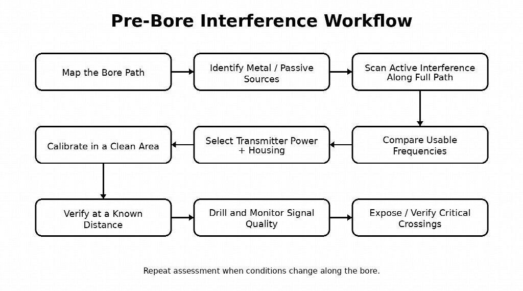
Figure 2. Pre-bore interference workflow. The sequence repeats when conditions change along the crossing.
11. Common Failure Patterns
The symptoms below do not identify one cause with certainty. They narrow the diagnostic sequence and help separate interference, calibration, configuration, and telemetry problems.
Table 7. Symptom-based troubleshooting matrix
| Symptom | Likely cause | What to check first |
| Depth suddenly becomes unstable | Active interference, passive distortion, or calibration problem | Compare frequencies, check calibration, identify nearby metal |
| Bore-path scan looks clean but depth becomes questionable under pavement | Passive interference | Check for rebar or wire mesh; evaluate supported low-frequency modes |
| Signal steadily weakens with depth | Reduced signal margin, housing attenuation, power/frequency issue | Check power, frequency, housing, and range forecast |
| Strong signal but implausible depth near steel | Passive field distortion | Do not rely on signal strength alone |
| Good readings at entry but poor readings farther along | Changing interference environment | Reassess conditions along the bore path |
| Locator receiver works but drill display loses information | Telemetry problem | Check the receiver-to-display link |
| Depth is consistently wrong even in a clean area | Calibration or configuration issue | Recalibrate and verify at a known distance |
12. A Reliability Model for Interference-Affected Bores
No single variable controls HDD tracking reliability under electromagnetic interference. A more useful model combines the factors that can change the received signal, distort the field, or undermine the interpretation of otherwise valid data.
Locator reliability = interference type + frequency suitability + signal margin + transmitter output + housing performance + calibration quality + receiver processing + operator verification
Each term can become the limiting factor. A high maximum-depth rating does not help when the operating channel overlaps strong active noise. Broad frequency flexibility does not guarantee correct depth beneath severe passive interference. High transmitter power can improve signal margin but cannot guarantee correct field geometry around steel. A capable receiver cannot compensate for poor calibration.
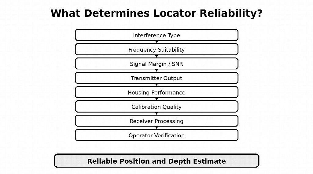
Figure 3. Reliability depends on the full locating chain rather than on a single specification.
13. Comparative Evidence: What Can and Cannot Be Concluded
The cited documentation supports comparison of available controls and stated limitations. It does not support a universal winner.
No independent controlled test in the source set demonstrates that DigiTrak Falcon or SuperCore, Subsite Marksman Plus, or Underground Magnetics Mag X is universally the most reliable when interference type, depth, housing, calibration, and operating conditions are held constant.
The defensible comparison is therefore project-specific. Crews should match the platform’s frequency options, interference-analysis tools, transmitter choices, housing compatibility, and verification workflow to the expected conditions of the bore.
14. Used Equipment: Interference Capability Should Be Part of the Inspection
Interference-management capability also matters when evaluating used locating equipment. An older fixed-frequency system can work well on a clean job, but it provides fewer options when its operating frequency overlaps a strong interference source.
Before purchase, verify:
- exact receiver generation and supported transmitter models;
- frequency range and low-frequency or Sub-k capability;
- transmitter power options;
- interference-analysis, SNR, or noise-floor functions;
- calibration repeatability and known-distance depth accuracy;
- housing requirements and transmitter compatibility;
- software or firmware compatibility;
- remote-display compatibility and telemetry condition;
- service support and transmitter availability.
15. Practical Reliability Test
The most useful reliability question is not which system advertises the deepest range or the largest number of frequency options. The stronger test is whether the crew can recognize degraded conditions before those conditions affect steering decisions.
Confidence should increase when several independent indicators agree:
- the electromagnetic environment has been surveyed along the route;
- the selected frequency performs consistently along the crossing;
- the transmitter has adequate signal margin;
- the housing meets manufacturer requirements;
- calibration has been verified;
- depth and position readings remain stable;
- critical utilities have been independently exposed or verified where required.
Confidence should fall when those indicators begin to disagree. Electromagnetic interference does not create one repeatable failure mode; it increases uncertainty in the locating data through different mechanisms. A reliable field process detects, measures, and manages that uncertainty before the bore depends on a questionable reading.
References
The list below reproduces the source base identified in the supplied draft. Manufacturer documents support product-specific features and specifications; the SAE document provides industry guidance. The draft does not cite a controlled independent head-to-head accuracy study.
Reference list
| Source | Type |
| Subsite Electronics, Marksman Series Operator’s Manual | Manufacturer manual |
| Subsite Electronics, Marksman and Marksman Plus product documentation | Manufacturer product documentation |
| Underground Magnetics, Mag X Operator’s Manual | Manufacturer manual |
| Underground Magnetics, Echo 75XF transmitter specifications | Manufacturer specifications |
| Digital Control Incorporated, DigiTrak Falcon and SuperCore documentation | Manufacturer product documentation |
| Digital Control Incorporated support documentation on incorrect depth readings, transmitter housings, and telemetry troubleshooting | Manufacturer troubleshooting documentation |
| SAE International, J2519_202601 — Guidelines and Procedures for Horizontal Directional Drilling (HDD) Machine Tracking Equipment Operators | Industry standard / guidance |